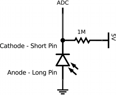
The following schematic demonstrates a simple infrared (IR) photodiode circuit using a analog-to-digital converter (ADC) to monitor the photodiode. An analog pin on an Arduino used with the analogRead() function will do the job. Photodiodes are two-pin analog devices. This makes them relatively easy to use and makes their output graded. Some of my students are using one in a project along with an IR LED as an IR absorption meter. On the other hand, their output is relatively weak so they can’t detect extremely small or distant IR signals. Notice that the photodiode is reverse biased. Thus, when no light is present, no current flows through the diode and the 1 megaohm pull-up resistor ensures that the ADC monitoring the photodiode reads 5 V. When light, in this case IR light, strikes the photodiode, electron-hole pairs are created in the semiconductor which creates a small current causing the voltage at the ADC pin to drop. So the lower the voltage read by the ADC, the more IR light is being received.

Permalink //
Many thanks for this! I wired up a scaled-up version of this to track terminal velocities on seeds dropping through a tube, and it worked like a charm.