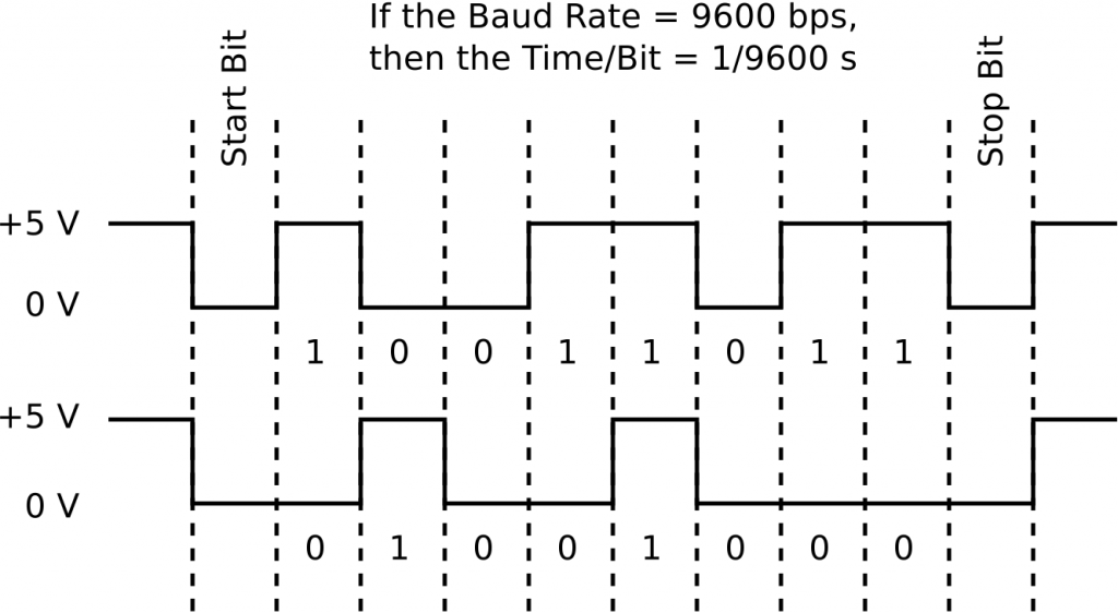
Serial communication between computers and/or microcontrollers allows messages to be sent using a single wire. The message takes the form of a series of voltage pulses that encode a sequence of zeros and ones. There are two main protocols for serial communication, TTL and RS232. The major difference between the two is the voltages that encode the bits. TTL encodes zeros with a voltage of zero and ones with a voltage of 5 V (or 3.3 V). To increase data integrity, RS232 encodes zeros as +3 V and ones as -3 V.

To establish a serial connection between two devices, the devices must share knowledge of the baud rate at which the transmission of data will occur (this is the number of bits per second (bps) being transmitted), the number of data bits in each “chunk” of data, the number (and value) of start and stop bits that will indicate the beginning and end of each “chunk” of data, and the presence (or absence) of a parity bit for error checking. The devices must also know whether the data stream being sent has the least significant digit or most significant digit first.
For Ardunio users, serial communication uses the TTL protocol. Data is sent in chunks of eight bits or one byte. The least significant bit (LSB) of the byte is sent first. The start bit and stop bits are low (0 V), and there is no parity bit. The baud rate can be set to 300, 1200, 2400, 4800, 9600, 14400, 19200, 28800, 38400, 57600, or 115200 bps. Usually, a rate of 9600 bps is used. Luck for use, the Arduino library has built in commands for using the ATmega328’s UART hardware serial channel so implementation of serial communication is a snap.
The figure above is an example of what an actual Arduino TTL serial signal would look like if it was monitored using an oscilloscope. Because the LSB is sent first, the numbers being sent are 11011001 (top) and 00010010 (bottom).